Auto-Polarization Switches
Automated testing of multi-element phased arrays with individual elements is now possible with our new multi port switch arrays configurable from 2 to 36 ports, and up to 40 GHz. An external switch controller enables stand-alone control along with real-time switch monitoring. The unique head mounted design allows the entire switch matrix to rotate along with the AUT, this eliminates the magnitude and phase errors associated with cable flex.
Educational discounts are available for students, teachers or staff of universities or technical schools.


Key Features & Functions
- Unattended multi antenna element testing
- Configurable from 2-36 Ports
- Serial over USB remote control
- Fiber Optic connection from controller to matrix
- Interfaces directly to DAMS Antenna Measurement Studio software.
- Wear monitoring for mechanical switches
Highlights
- Easily switch through 4 ports
- Intuitive design
- Remote control option
What's Included?
A standard switch matrix package features:
- Head mounted switch matrix
- DUT Side radial connector panel
- Interconnect Cables
- Desktop/Rack mount controller
- matrix power supply (located in chamber)
- 50′ Fiber optic cable with ST connectors
- Power Cord
- User’s manual
Specifications
Operating Specifications
| Frequency range | DC to 40 GHz |
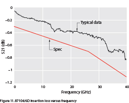
| Insertion loss | 0.3 dB + 0.015 x freq. (GHz), DC to 26.5 GHz |
| 0.030 x freq. (GHz) – 0.1 dB, 26.5 to 40 GHz | |
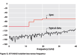
| Isolation | 100 dB minimum, DC to 12 GHz |
| 80 dB minimum, 12 to 15 GHz | |
| 70 dB minimum, 15 to 20 GHz | |
| 65 dB minimum, 20 to 40 GHz | |
| SWR | 1.3 maximum, DC to 4 GHz |
| 1.35 maximum, 4 to 12.4 GHz | |
| 1.5 maximum,12.4 to 18 GHz | |
| 1.7 maximum, 18 to 26.5 GHz | |
| 1.95 maximum, 26.5 to 40 GHz | |
| Repeatability | 0.03 dB maximum (Up to 5 million cycles measured at 25 °C) |
| Connectors | 2.92 (F) |
Switch Specifications
| Parameter test (units) | Conditions | Min | Nom | Max |
| Supply voltage, Vcc | ||||
| Option 024 and T24 (V) | 20 | 24 | 32 | |
| Supply current, Icc | Switching pulse width ≥ 15 ms: Vcc = 24 VDC | |||
| Option 024 and T24 | 200 | |||
| Supply current (quiescent) | ||||
| Option 024 and T24 (mA) | 25 | 50 | ||
| Option T24 | ||||
| High level input (V) | 3 | 7 | ||
| Low level input (V) | 0.8 | |||
| Max high input current (mA) | Vcc = Max; Vinput = 3.85 VDC | 1 | 1.4 |
Typical Profiles
Mechanical Switch Models
DSM36-18: 36 port mechanical matrix (7x SP6T) with terminated ports and SMA connectors SP36T configuration
DSM36-40: 36 port matrix (7x SP6T) with terminated ports and 2.92mm “K” connectors, SP36T configuration
PIN Switch Models
DSP-36-40: PIN Diode switch matrix (2 x 18 port) terminated with 2.92mm “K” connectors
Switch Controllers
SC100 Controller: Switch matrix controller with USB and Fiber Optic interfaces – rack mountable.
Additional models available. Please click below to request a quote.
Quote RequestOptions
No additional options available at this time. For unique requests, please Contact Us
Customer Support
Diamond Engineering takes great pride in providing top-notch customer and technical support. If you are having any issues with your system, we welcome you contact us directly. We can walk you through or suggest solutions to any issues you may have.
Please don’t hesitate to contact us.
Read moreMicrowave Library
If you have not already reviewed the materials in the Microwave Library, we encourage you to. There you will find numerous application notes detailing how to accomplish many types of tasks.
To visit the Microwave Library, click here.
Read more